denson1932
Well Known Member
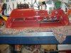
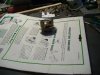
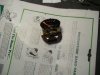
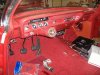
today's progress got the instruments cleaned and installed into the freshly painted dash....now to figure out where all those wires go.....
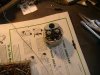
That sounds crazy and like extra work! But it turns out it's not! That is how it was done at the plant. It's much easier and quicker making all the correct connections and double checking your work on a bench than looking backwards with it sitting on your knees.It is much easier if you remove the two screws attaching the fuse block and remove the entire dash harness and install it to the dash panel on the work bench. Then take the entire assembly and install it in the vehicle. Also, your cowl vent grills should be painted satin black.
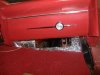
since i have the padded dash option on the drivers side only (was deteriorated but i patched it and painted it just for the patina effect) do i need the black rubber U-shaped trim on the edge of the dash also?
I guess he told you Dan!!!!!!!!!Paul, thanks for the excellent tips and aids on the wiring sequence and dash assembly...
since i have the padded dash option on the drivers side only (was deteriorated but i patched it and painted it just for the patina effect) do i need the black rubber U-shaped trim on the edge of the dash also?
Good eyes, you noticed the pass side dash, but look closely... the driver's dash also has the 'Impala' trim masked and painted...just trying to do the car a little different (like satin red not satin black vent grills). Confucius sez: " Man who pays bill picks own colors".


Guess so...I guess he told you Dan!!!!!!!!!