With your awesome torque, adjust rear suspension set up and instant centre etc accordingly and fit the biggest meats under the rear as possible and gear from there

Concrete bed floor.How in the world are you going to get this to hook up?


How long ago did you order your wiring harness? The FAST stuff I got earlier this summer was nearly idiot proof. All the connections were marked and everything was neatly wrapped in a wire loom. This is true of the EFI and coil pack controller.Dammmmmm. I wish I had thought of that kinda shield earlier!, great callout la.. We do have one but it's the thin kit kind.. hopefully that and the double thick tunnel we used helps protect us...I'll dig up a pic
Yesterday was a wiring day for the efi system and ignition system from FAST and the instructions qere/are terrible! Not like a simple writing diagram saying connect this to your that so we called and the guys there were great.
The first call we had we tagged every end and went over it again before we let the guy drop. Then because I'm a paranoid sob I called again got another guy and went through it all of the wires again and found one that the first dude had me use wasnt supposed to be..
They had me wire it to use the ecu for electronic timing, so the system can change timing with a button. Before we start the truck, we have witness marks on the dizzy and manifold and can always block that out...
Soooo, today is now all about getting the wiring in its final place, cleaning everything up and prepping for the swap. The header kit showed up yesterday. I'll open today and take a pic...
How long ago did you order your wiring harness? The FAST stuff I got earlier this summer was nearly idiot proof. All the connections were marked and everything was neatly wrapped in a wire loom. This is true of the EFI and coil pack controller.
Glad to hear their phone/tech support was good to deal with.
Well yesterday was that day! Seems like any big build for us theres a day thats on paper looking like a cake walk but turns out to be an royal pain, yesterday was it!
Clocking that bell took hours! The dial indicator was a pain to fidget with, have to get it flat on the flywheel but somehow trace the inside diameter of the transmission hole and not bump it with the dial housing, knobs etc . Couldn't get it too close or the plunger bottomed out, too far and it would run out.. then you get it mounted, avery turns the motor around and freak because it travels. 11 and divided in half its .055 and that's more then. 05 and start over..
The start over is taking off the bell, grab a wrench and with very quiet hands try not to twitch and turn the offset dowel pin just a degree or two, a hair on both sides.
Sounds easy on paper but its tricky and after hours wouldn't accept anything less than correct and luckily had all three sizes of pins and ended with .02 :>) which is in spec, wheeeeeew...
After that, we still had to take the bell off two more times. One to put on the clutch and pressure plate, then have to measure the bell hole down to the fingers of the clutch plate. For us that was 2.10 and then at the trans, put on the hydrolic throw out bearing and measure the face of the trans to the end of the throw out bearing, 2.10. Of it's more than .15 add shims. We were within so the bell comes off again, then you pull off the throwout bearing, and can finally install the bell for the final time, add the throwout bearing and connect to the engine..
Only bad thing, were ready for our first 5000 mile oil change cuz we turned it over a few times. Hahaha.
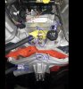
Today should be install day. We took our time on everything to this point, bay is clean and took a lot of time to mount the coil next to the booster. Had to actually take off the booster to drill the holes, but its away from the ecu and ignition box on the passenger side. We are a little nervous that the coil could hit the valve cover near #7, well see..
Oh, we backed up the truck on ramps to get more angle and notice the pressure plates. The one with the finger separation was the one we have been using so went with it again but they it is different from the other new one we had kicking around.
,
 Really happy for you that things have been going so well. When I left, I had a bad feeling that you were going to be struggling to get that engine ready to go into the engine bay by the weekend.
  Better get it done between today and Monday night, because Tuesday is expected to be a scorcher in the high 90's. Junk
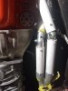


Those are some pretty tight bends at the ports.
Was there a chance you could bring the tubes over the frame rails and then down and back?