You are using an out of date browser. It may not display this or other websites correctly.
You should upgrade or use an alternative browser.
You should upgrade or use an alternative browser.
Durg's 65 SWB BBW Fleet build
- Thread starter Kdurgin
- Start date
nice job can't go wrong with porter built stuff.


Kdurgin
Well Known Member
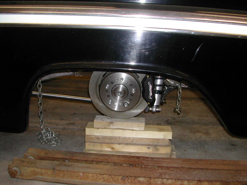
This is at 5-1/2" in the front and 6-1/2" in the rear as measured from the floor to underside of main frame rails directly below front and rear cab mounts. I have sent Nate my upper control arm and rear four link arm angles to get a recomendation. I also have been working on the rear bed frame some more gearing up for the wood install.

Kevin,
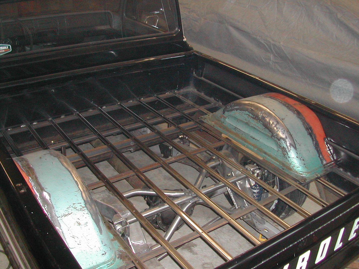
I noticed you used two wheel tubs to widen your rear wheel tubs. May I make a suggestion to widen your 4-outer boards both forward and aft of the wheel tubs and leave the cut out board around the wheel tub the same width with the same reveal from the bed strip to the wheel tub. Then narrow the two center boards to make up the difference. I build the bed kits all the time for people and have done this several times. I am building a kit for a guy next week.
Look here. http://www.gmcpauls.com/47-72_BedWood_Info.htm

Late 1960 to 1972 Fleetside - 12 Boards
2- 6 3/8"* 7 7/16 7 7/16 7 7/16 5 7/16 5 7/16 7 7/16 7 7/16 7 7/16 2- 6 3/8"*
Late 1960 to 1972 Fleetside - 12 Boards
I noticed you used two wheel tubs to widen your rear wheel tubs. May I make a suggestion to widen your 4-outer boards both forward and aft of the wheel tubs and leave the cut out board around the wheel tub the same width with the same reveal from the bed strip to the wheel tub. Then narrow the two center boards to make up the difference. I build the bed kits all the time for people and have done this several times. I am building a kit for a guy next week.
Look here. http://www.gmcpauls.com/47-72_BedWood_Info.htm
Late 1960 to 1972 Fleetside - 12 Boards
2- 6 3/8"* 7 7/16 7 7/16 7 7/16 5 7/16 5 7/16 7 7/16 7 7/16 7 7/16 2- 6 3/8"*
Late 1960 to 1972 Fleetside - 12 Boards
Kdurgin
Well Known Member
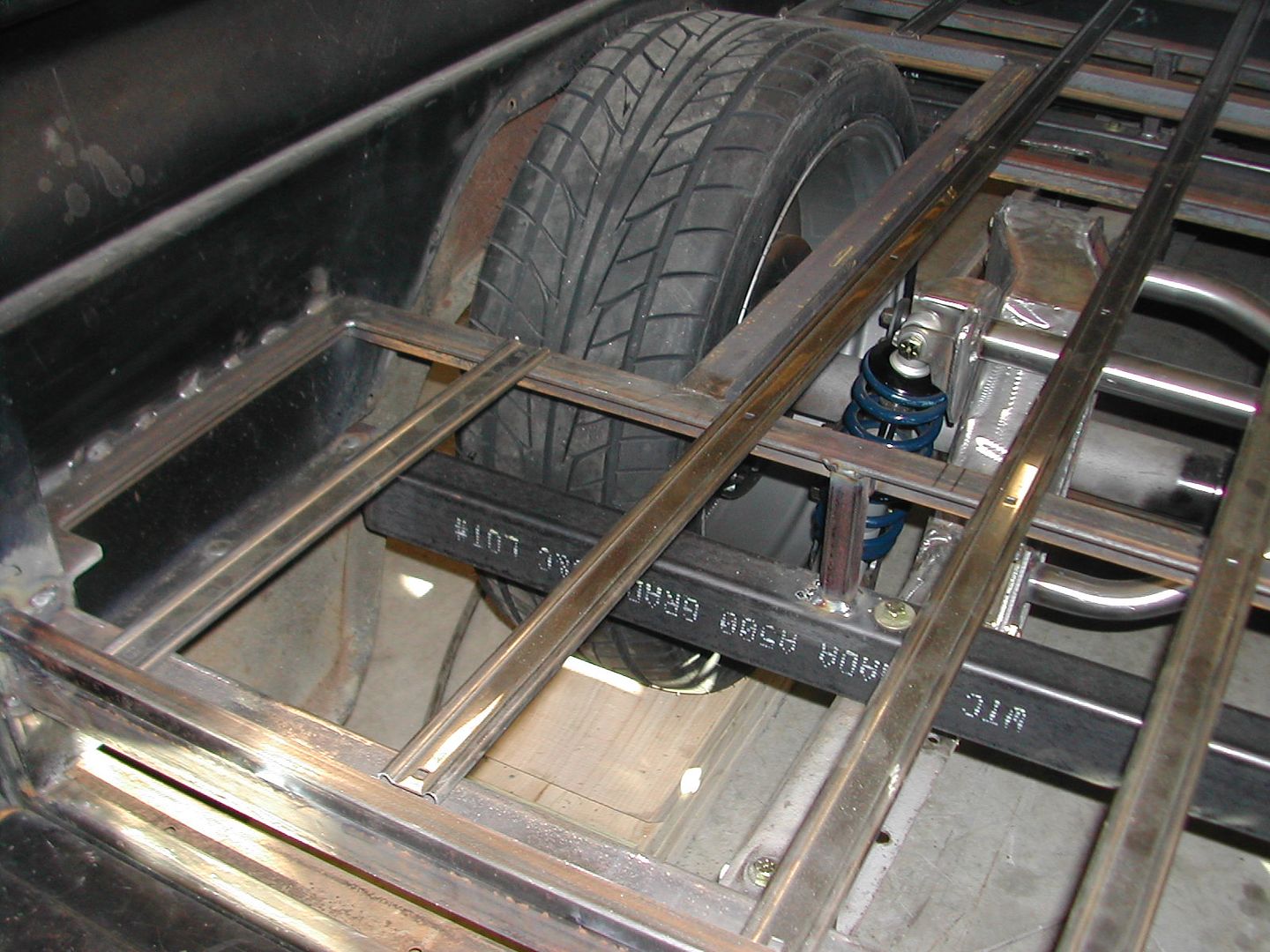
I THINK my second board in is going to look the one in your picture. Maybe toward the tub 3/4" or so ? I was then going to have all the other boards except for the 2 outers on each side, the same width. As I already have all the boards and need to rip them all to width, what would be the disadvantage of having all 6 middle boards the same width? I think it would look better. Any feedback is definately welcomed though!
The problem with having the inside seam of the second board closer to the tub is there is not very much material left. You have a rabbit on the inside of the board and then the holes on the outer for the tub. Its common to make all the boards the same width or as close as possible but don't try and cheat that second board. It will break if the there is much flex in the vehicle.
Its a hard for me to tell looking at your pics from the angel you took them but, it looks as if the width of your board at the wheel tub is only about 1-1/2" to 2" wide. Then you have a rabbit cut 3/4" X 1/4" and holes drilled on the other side. That does not leave much material left. It appears the bed strip is only 1/2" to 3/4" away from the wheel tub flange? It doesn't look right. IMO.
A=3/4"
B=1/4"
C=1/4"
D=1/2"
E=1/8"


A=3/4"
B=1/4"
C=1/4"
D=1/2"
E=1/8"
Kdurgin
Well Known Member
Merry Christmas all.
I have been slowly continuing some fabrication, repairs and mocking up some things.
At ride height, I have 1/4 degree camber with no shims so Nate is making me a set of upper a-arms 3/8" shorter.
I got the Porterbuilt panhard setup installed and final welded.
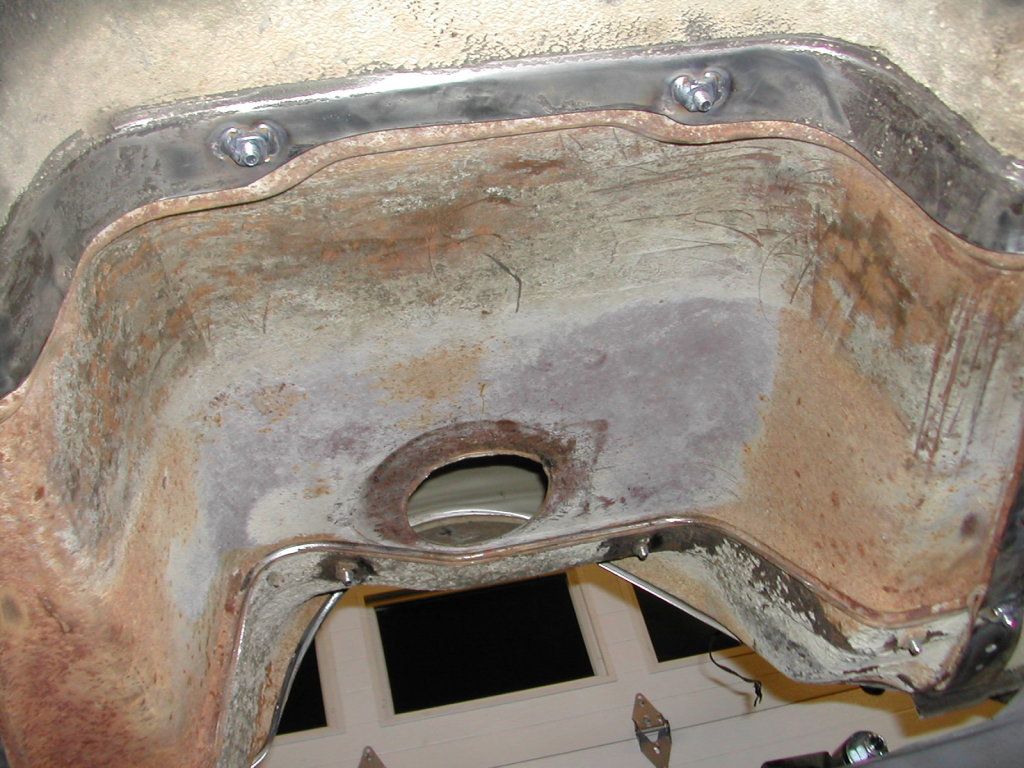
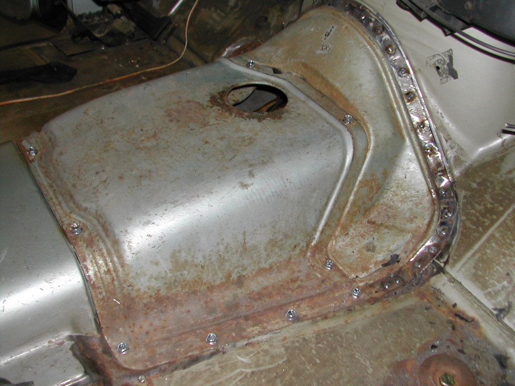
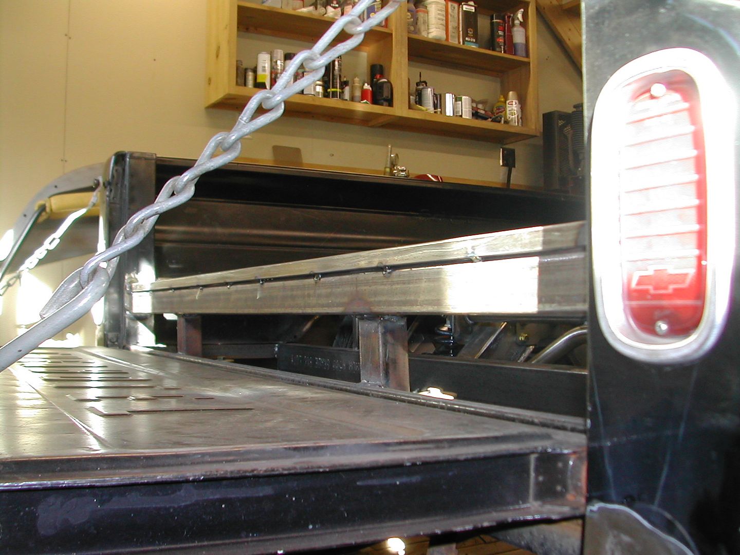
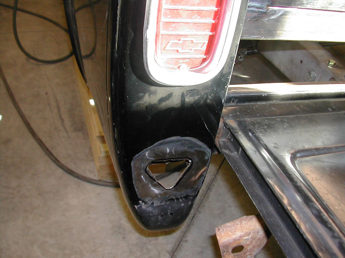
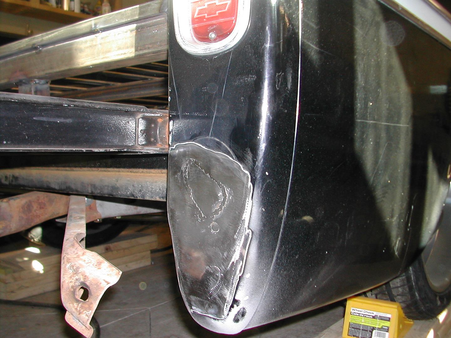
I have repaired one of the messes made on a set of step side type? rear back up lights that was installed and they drilled about six holes in each side when mounting so I cut out the areas with holes and welded in a patch. One side still left to do.
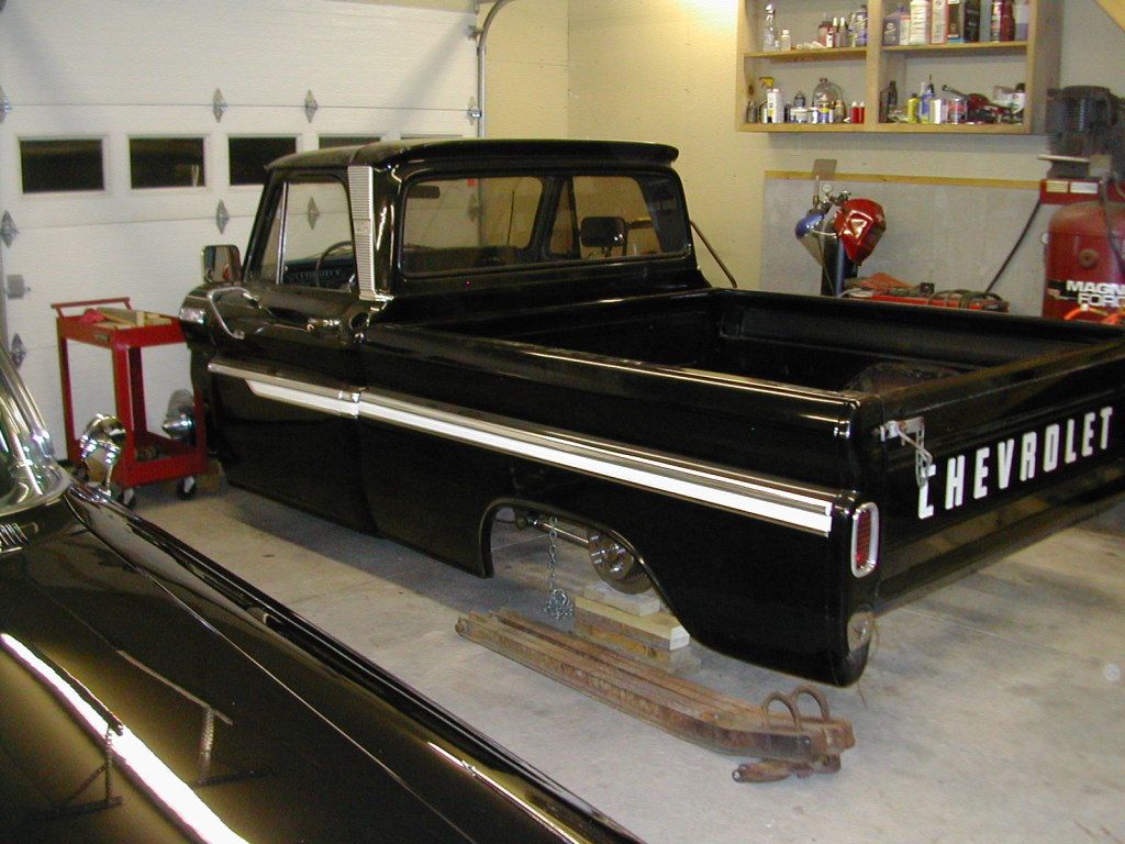
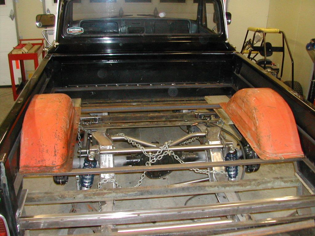
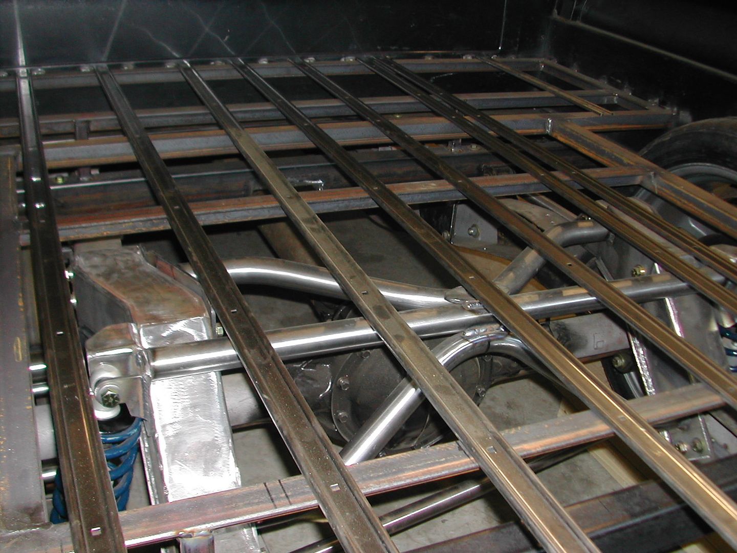
I have included a photo from the rear of the bed to see how high the bed frame is raised.
I got the rear sill 2x3 final welded and have put a few supports in from the sills up to the new bed frame.
I have been slowly continuing some fabrication, repairs and mocking up some things.
At ride height, I have 1/4 degree camber with no shims so Nate is making me a set of upper a-arms 3/8" shorter.
I got the Porterbuilt panhard setup installed and final welded.
I have repaired one of the messes made on a set of step side type? rear back up lights that was installed and they drilled about six holes in each side when mounting so I cut out the areas with holes and welded in a patch. One side still left to do.
I have included a photo from the rear of the bed to see how high the bed frame is raised.
I got the rear sill 2x3 final welded and have put a few supports in from the sills up to the new bed frame.
droptop62ss
Well Known Member
Looks great Kevin that thing is going to handle like no tomorrow !
Are you putting another stroker motor together for this one ?
Are you putting another stroker motor together for this one ?
Kdurgin
Well Known Member
Not sure on motor. I may start just putting the 327 back in it for awhile that came with the truck. I need to do a compression check on it to see how that looks. It leaked alot of oil but ran OK. Maybe a ZZ383 crate motor. I have time to decide. It will be a regular carbed SBC though with a regular fuel pump and the gas tank in the cab behind the seat.
Kdurgin
Well Known Member
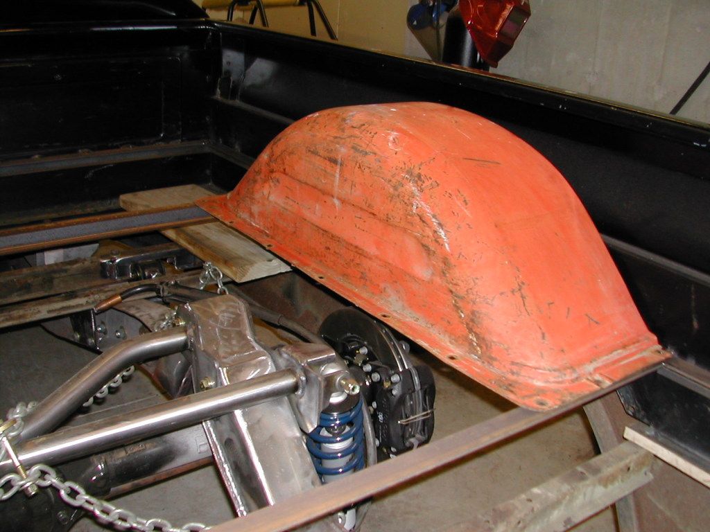
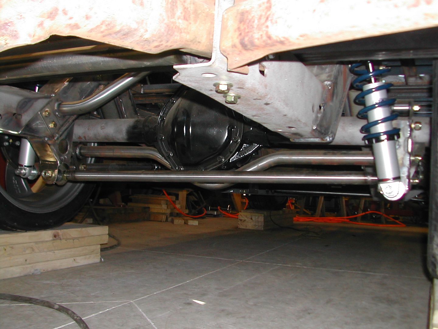
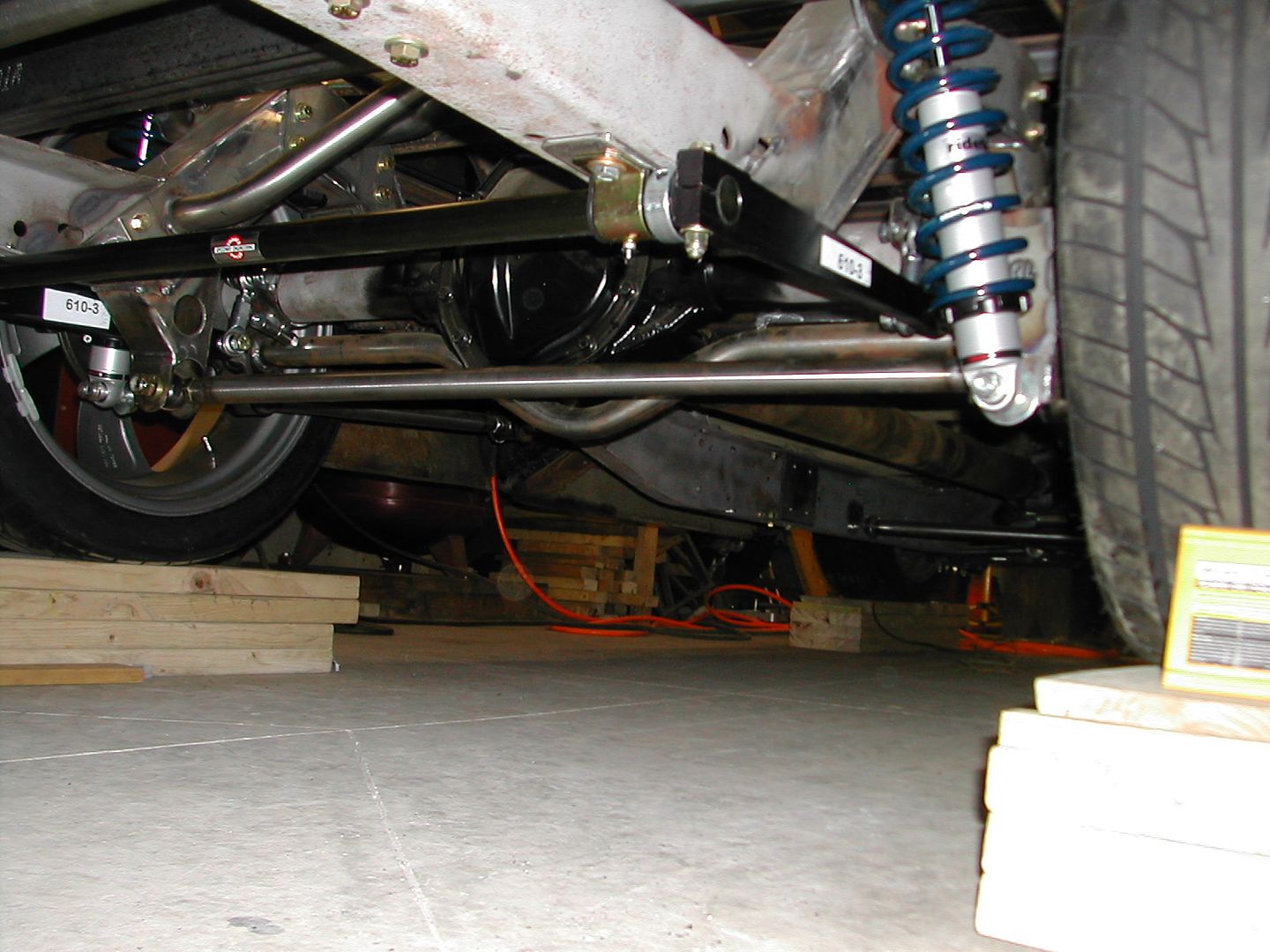
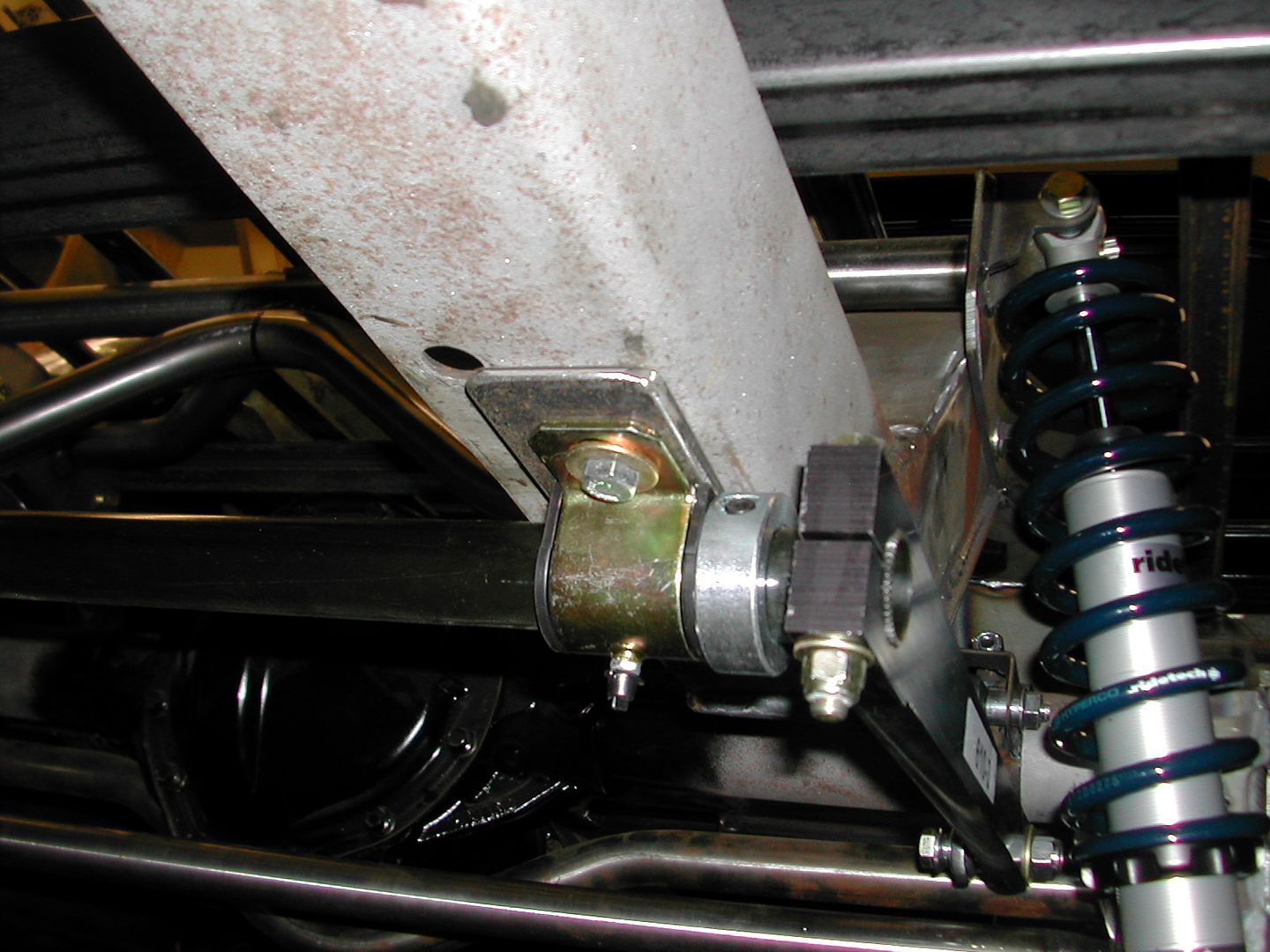
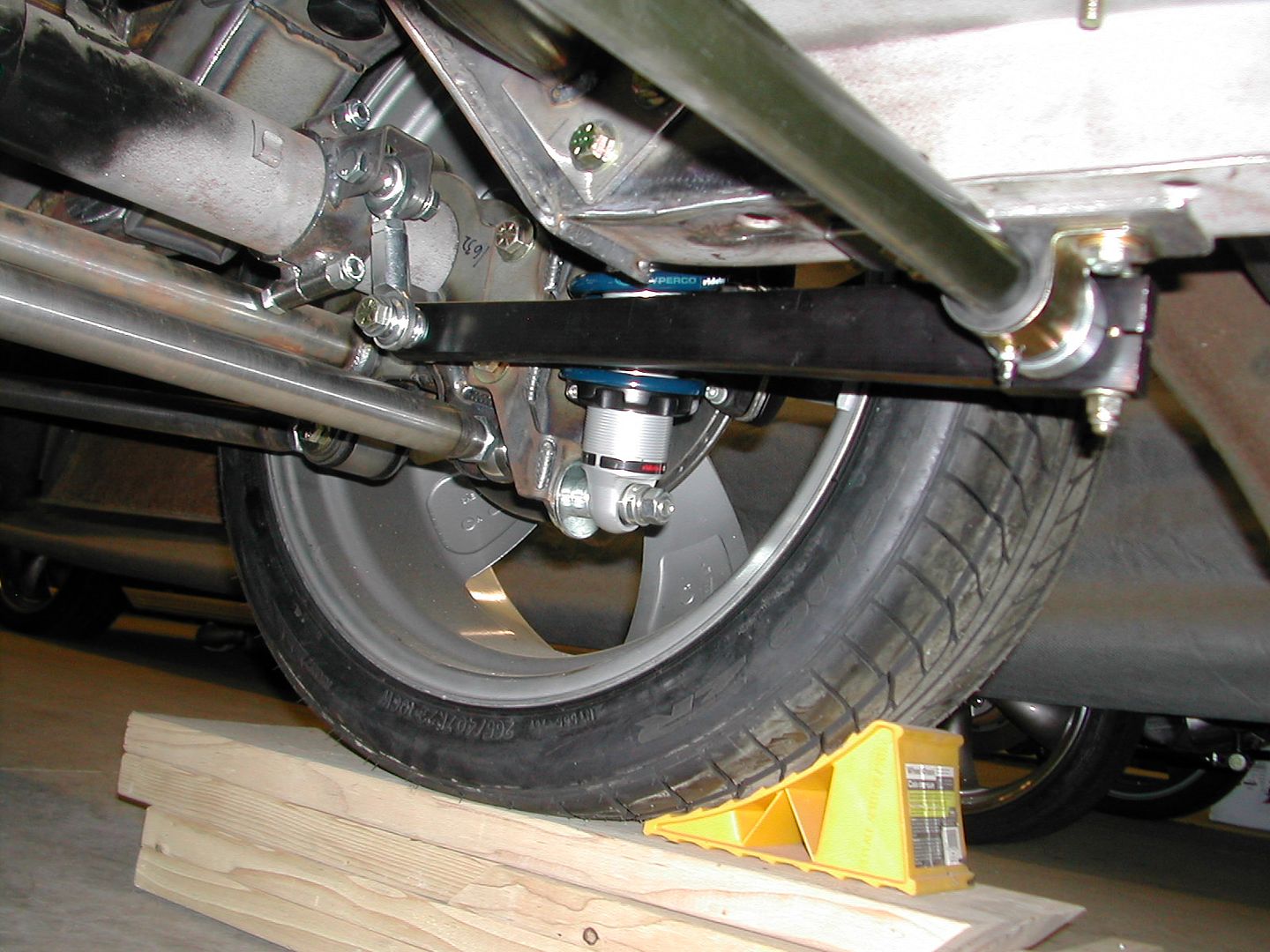
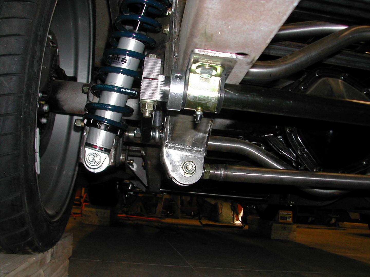
Rear suspension is now complete. The bolt on brackets will be welded and I will remove the top bolt and sleeves so as not to interfere with the bump stop installed on the underside of the notch. I will also need to weld up the 2 piece Porterbuilt rear end tube mounts when the pinion angle is final. I ended up with 15.5" long arms on the rear bar and it's 37.5 inches wide .095" diameter for a rating of ~175 lbs. @ 5 degrees of twist. I will probably drill some more holes in the arms just to make them look cooler when I tear the truck chassis back down for paint. I used the greaseable bushings. There does look like 10 pounds of shit in a 5 pound bag back here, but everything appears to have adequate clearance and should be fine.

Kdurgin
Well Known Member
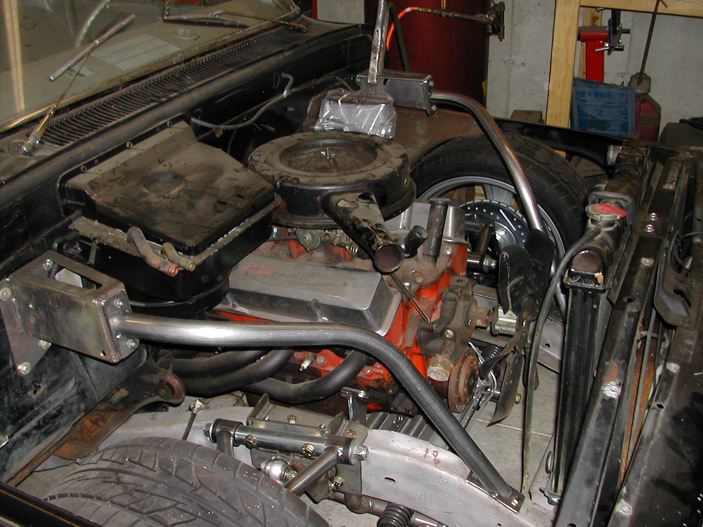
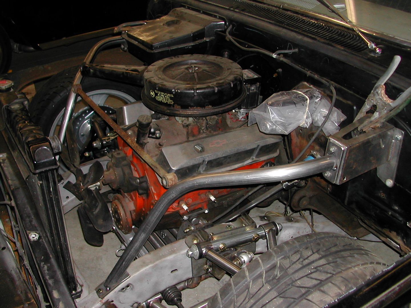
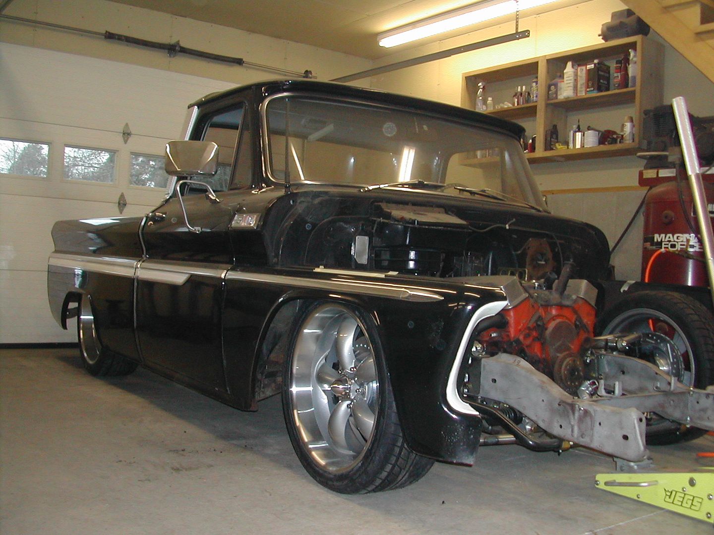
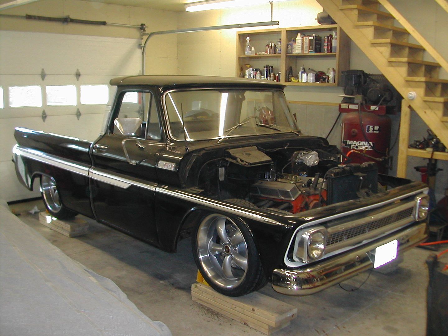
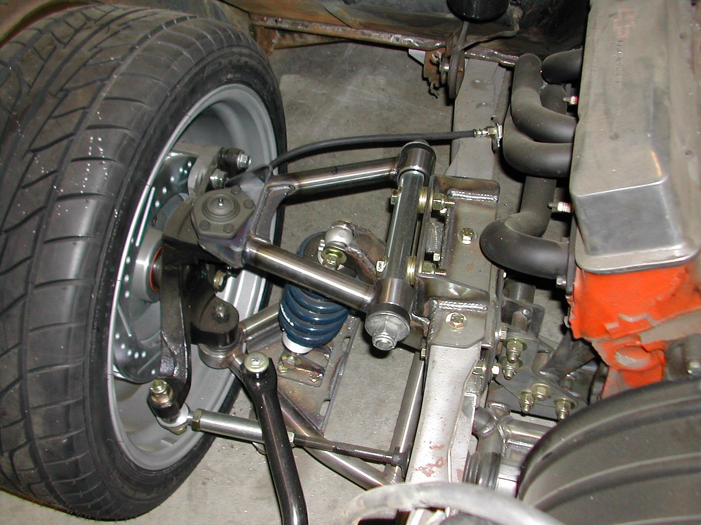
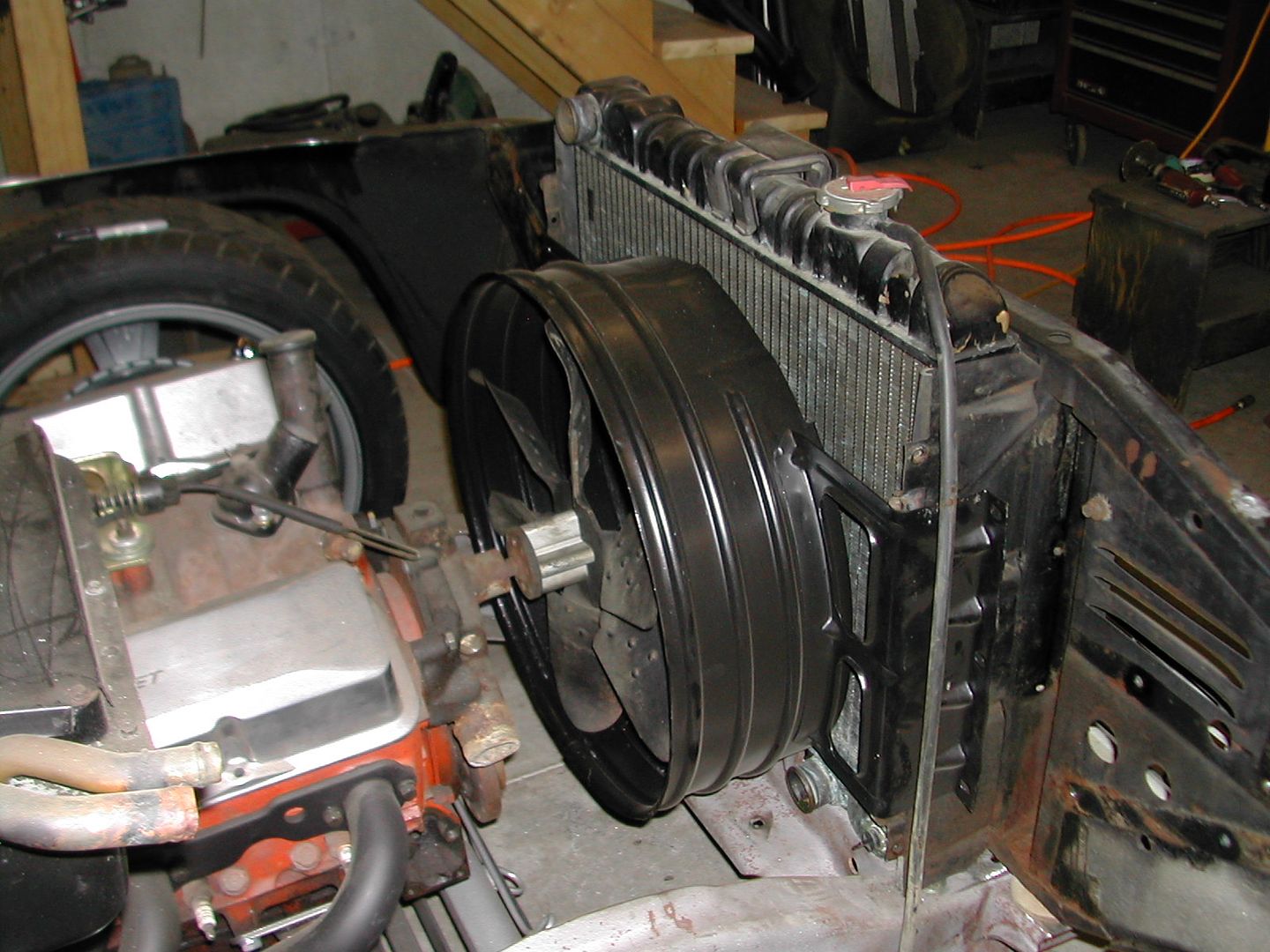
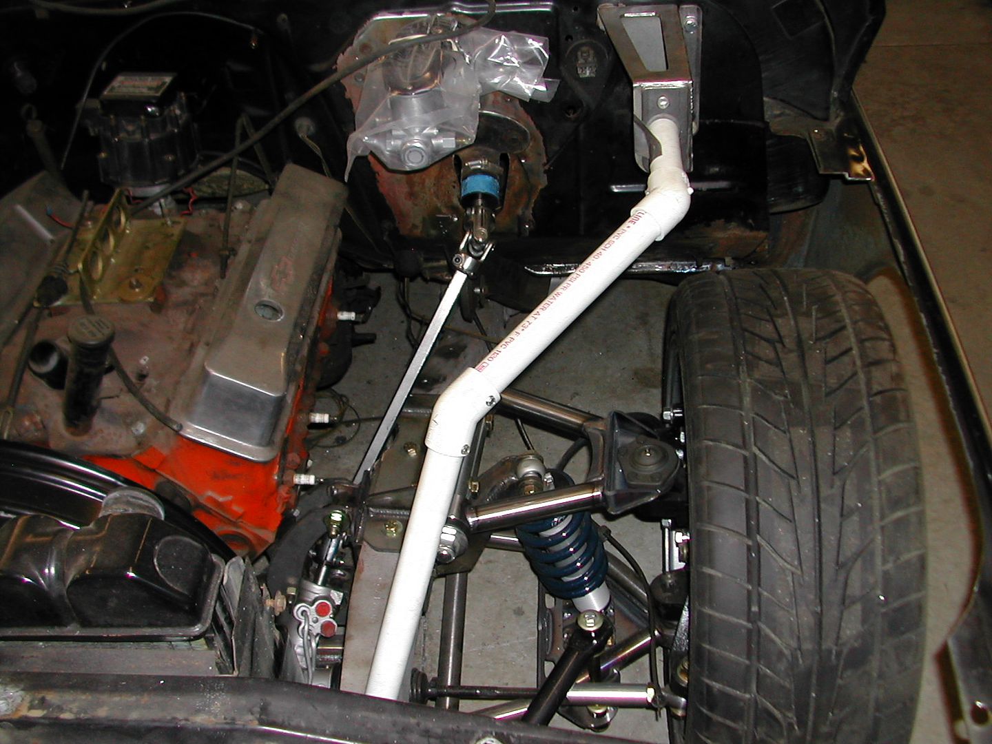
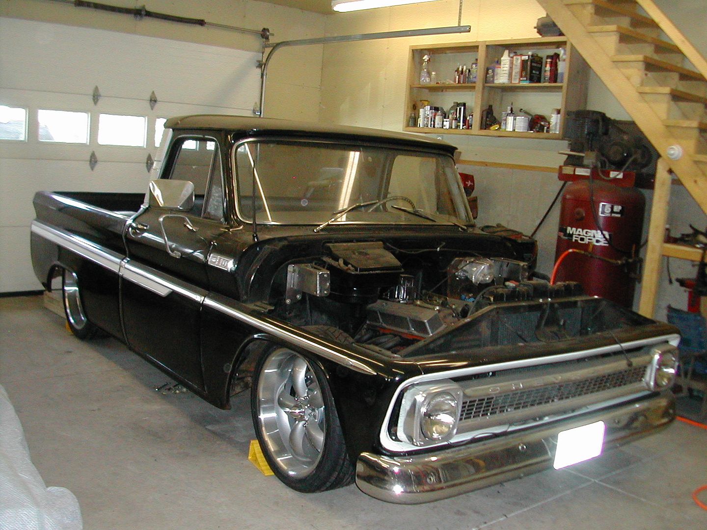
Few minor updates: Truck is back on the floor with the new a-arms installed with good adjustibilty on camber. I am toying with the idea of running a 61-62 style Impala barrel shroud as the stock fiberglass/plastic one won't be as easy to install as my radiator to engine height is different now. (I know the fan needs to move back to be centered) I used some PVC pipe to mock up how I want the front bracing to go. Went to get it bent yesterday at a near by racing chassis place but they were not working. I will be running a rod with heim ends from side to side connecting to where the lower elbows are shown on the braces. This will all be removeable. I am bolting a flat plate on the front frame horns that the braces will weld to on that end like onto the hood hinge brackets. Truck is shown at ride height.
Kdurgin
Well Known Member
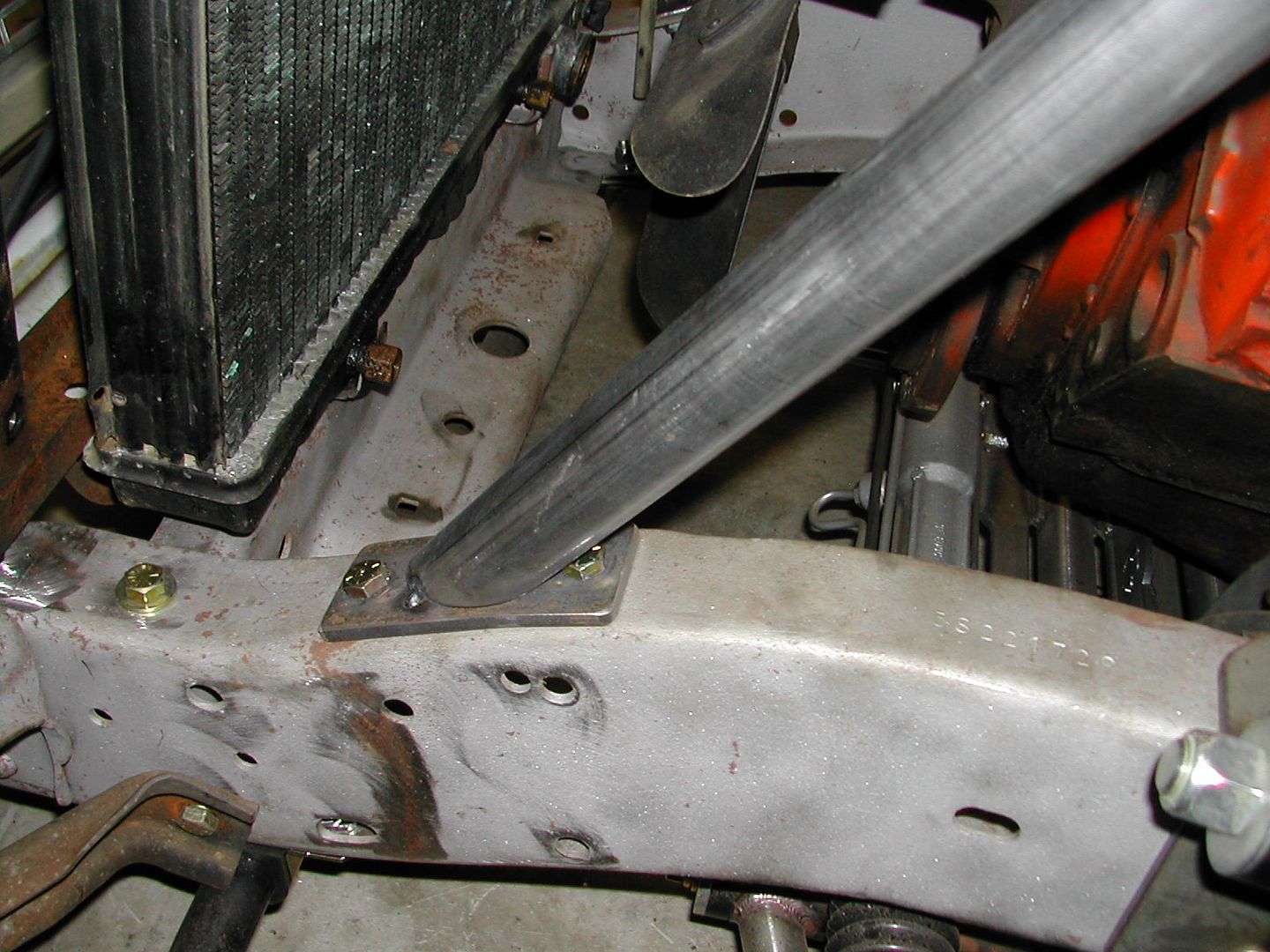
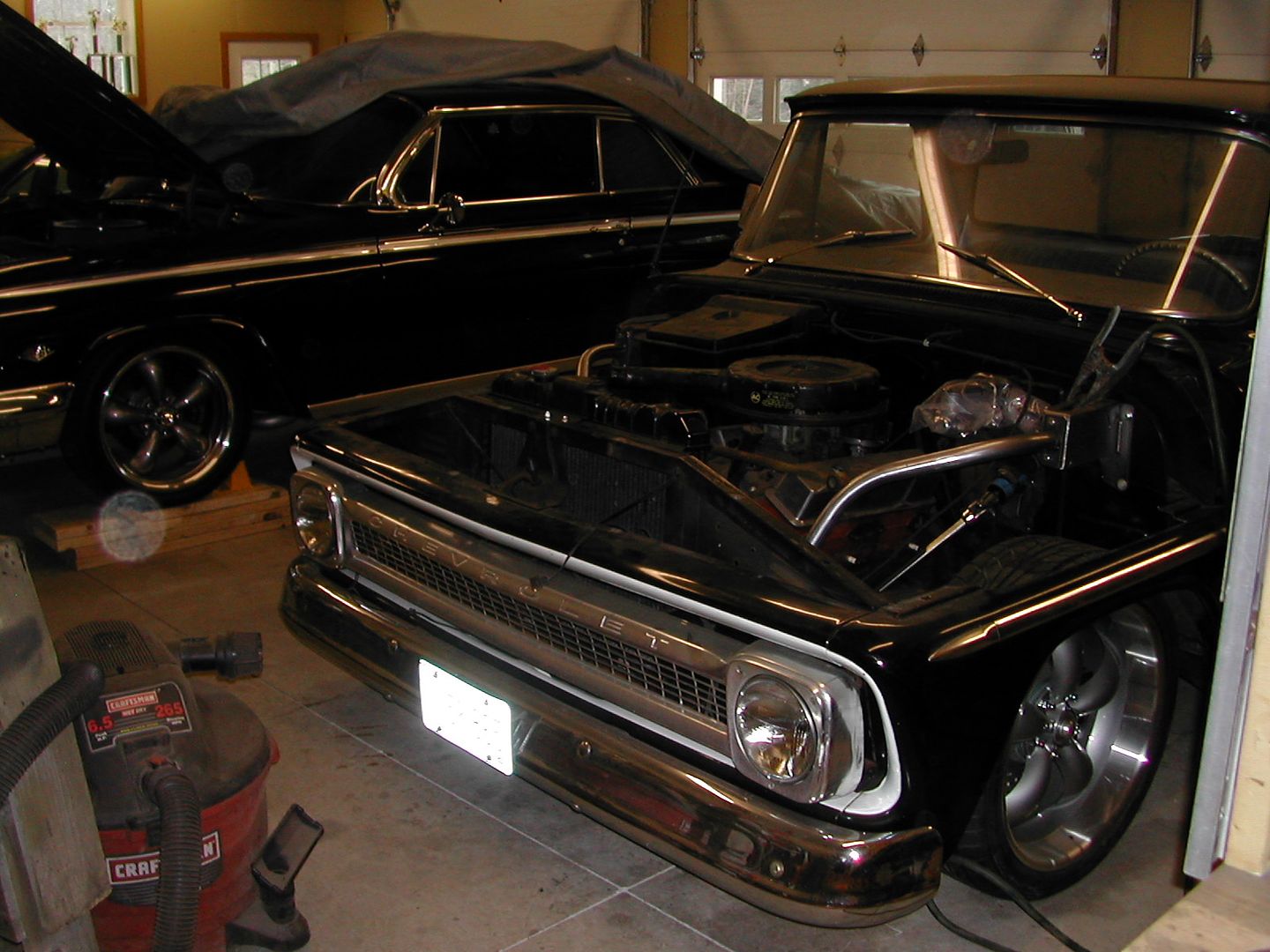
Got my front bracing roughed in down to the frame horns. There will be a cross brace to tie them together but I need to know where my accessory drive package will end up before I can commit to its location. I am leaning toward a GM Performance crate 350/330 setup with the front serpentine drive. The Impala twin is getting ready for spring. I still have snow on the ground here though.