The quest for more + caster

Jim Sullivan

Well Known Member
Supporting Member 10
I had am idea the other day while trying to figure out how to get more caster on My 63. I am going to see how this works, so all comments/criticisms are welcome.

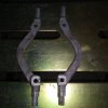
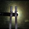
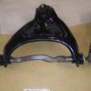
I turned down an upper control arm shaft in order to move the control arm more rearward. I took off about 3/8". Looks like there will be enough clearance on the frame. I am going to try and make a jig to check how this compares measurement wise to shimming the control arm. It may or may not provide enough of a change to make the effort worth while. We'll see. I'm not seeing where there would be a strength issue, but please let me know what I might be missing.
I will cut the machined piece down to original length and add spacers on the rear if the shaft.20190105_113259.jpg20190105_113251.jpg
 

Jim Sullivan

Well Known Member
Supporting Member 10
I see that making a huge difference. I had thought of making offset bushings for the mounting holes to gain more caster. I like your idea better.
Since I was fiddling around with the lathe, I thought I'd see if I could machine the shaft as a test. As long as I used a live center to support the end and very low rpm, it spun pretty true. So, now to set up a jig to find out if it will add as much caster as a "several shim" change would. I think I can even use our engine run stand to set up the control arm. We'll see.
 

ragtp66

Well Known Member
Jim,

I know someone else who was trying to get additional negative camber, after looking at what you are doing and thinking about it for a minute If you were to machine down the squarish blocks where the control arm mounts to the frame would it allow you to gain more camber even if its just a 1/16 or an 1/8th? My thinking is that effectively it would be the same as adding more shims pulling the top of the tire further inward, sometimes you run out of thread on the bolts with a fat shim pack or interference with headers etc. Not sure how much you could remove or if my thinking is off.

Chris
 

Jim Sullivan

Well Known Member
Supporting Member 10
Chris, I'm thinking about the machining that you mentioned. I did just that on the control arm shafts that are on my four door now. I believe I machined the mounting area down almost 1/4" with no problems to date. Once I can mock up a control arm on a frame, I'm going to check clearances with the machining that I just did and see if I can machine the mounting area also. I hope all of this makes enough of a difference to make it worth while. It would be great to pick up a couple degrees positive caster.
 

heddrik

Well Known Member
Very cool idea! If you could use a square plate with proper holes and a 4 jaw chuck ( if you have one) you could turn it faster on the lathe. Bolt shaft to plate and indicate it in, it wouldn't stick out very far either. good luck .
 

ragtp66

Well Known Member
Jim if you decide to do it please let me know how it works out. I found out the HARD way that the cross shafts can go in BACKWARDS and you figure it out when the upper control arm hits the frame on the side closest to the firewall. Sucks having to knock it all back apart without scratching up the powdercoating. :doh

Thanks
Chris
 

Jim Sullivan

Well Known Member
Supporting Member 10
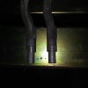
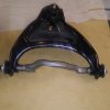
The cross shafts are finished, except for some deburring. Now to blast the control arms and assemble. I ended up turning the front bushing mounting area back 1/2", added a 1/2" spacer collar on the rear(l will add a 1/2" spacer to the rear bushing mounting area) and I machined 1/4" from the front frame mounting pad area. I machined a little more that this from the upper control arm cross shafts that are currently on my four door, with only a slight improvement. I hope all of this makes enough of a difference to make it worth the effort. Hopefully I can try these out by early summer.20190217_102101.jpg20190217_102120.jpg20190217_102128.jpg
 
Last edited:

Jim Sullivan

Well Known Member
Supporting Member 10
The four door has a completely stock suspension and power steering Don.
It actual drives pretty well but can get a little squirrelly at Highway speeds. What I would expect from a big car with less than 1/2 degree of positive caster.
 

Jim Sullivan

Well Known Member
Supporting Member 10
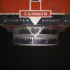
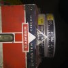
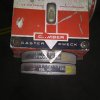
Control arms are installed and I started to align.the front end. Camber is set at +5/8 degree driver side and +1/2 degree on the passenger side. Best of all, with the upper control arm shaft modification, caster is approximately +4 degrees both sides. Can't believe it came out that high. Saturday I have to install the steering shaft and set the toe and the steering wheel.

Now I can't wait to drive down the highway and see how (hopefully) stable the car is. That will be a few weeks while waiting for my headers to be coated.
Driver side caster
20190606_201951.jpg
Camber
20190606_202038.jpg
Passenger side camber20190606_202547.jpg
Caster20190606_203253.jpg
 

Jim Sullivan

Well Known Member
Supporting Member 10
With adjustable control arms on my 62, I had either 5 or 7 degrees of caster. Drove like it was on rails! A bit harder to turn as the car has no power steering. You will be amazed at the difference.
That's what I'm hoping for Brian. Except the harder to turn part, but I've got power steering so that shouldn't be an issue. Its the stability on the highway that's most important!
 

montemike79

Well Known Member
We are going to copy your idea with machining the shafts on my dad's '61 Impala. His camber and caster is out and we have no adjustment due to frame sag. I'm curious how far yours was out of whack before you did this ?
 

Jim Sullivan

Well Known Member
Supporting Member 10
We are going to copy your idea with machining the shafts on my dad's '61 Impala. His camber and caster is out and we have no adjustment due to frame sag. I'm curious how far yours was out of whack before you did this ?

Before the modification, the caster maxed at about 1/2-3/4 degree positive while keeping the camber about 1/2 degree positive. The modification increased the caster more than I thought it would and I'm very happy with the results. Now I just have to test drive it to see how it handles.

One word of caution, the upper control arm shaft ends, where the bushings press on, are not lined up as close as you would think. I ran the lathe at is lowest speed(also because of the offset) and used a live center. I had to tweak the shafts a little in the press to get them straight enough to turn in the lathe.
 
Last edited:

montemike79

Well Known Member
Thanks for the info. Your car wasn't out bad at all. His car has about -1 degree of camber and -3.5 on the left and -4.3 on the right of caster. And that is with almost no shims. We tried playing with shims but we gain a little caster then we lose the camber so we are stuck. The alignment machine is calling for -.5 to .5 degree caster. We were going to turn the shafts like you did but instead only mill 1/8" since you said you tried that before and didn't gain much with just that. I wonder if we could turn the shafts back a little more than 1/2" to gain a little more caster ?

One other question while I am thinking, are you maxed out 4 degrees of caster, or could you put more in it ?
 

Jim Sullivan

Well Known Member
Supporting Member 10
There is still more clearance on the control arm mounting bracket on the frame so you may be able to go a little more than the 1/2" I machined. Maybe up to 3/4"? I still have a little more adjustment, I didn't want to max it out. Your frame sounds really out of whack with those measurements. If you haven't already you may want to look the frame over really well and make sure there is no visible damage before trying the control arm modification. I've aligned several x frame cars over the years and haven't seen one with measurements that negative. Stupid question, are the control arms on the correct side? They probably are or you might have even more negative caster. Just thinking out loud.
 

montemike79

Well Known Member
They are on the right side, I don't think they have ever been off. This car is all original, down to paint and body, so we know it was never hit. It is a 348 car so maybe that contributes to more frame sag ? The best solution would probably be a pair of tubular upper arms with caster built in, but this car is all original and those would stick out when you open the hood so we were trying to come up with a different solution. I've been watching this post since you first started it hoping this was it. If you can still put more caster in it, then maybe what you did would be enough to put his car in spec. That's all we're after at this point. I appreciate your help.
 

Jim Sullivan

Well Known Member
Supporting Member 10
You might want to pick up a second pair of of used control arms/shafts to modify. Save the originals. How are the bushings?
My 63 SS that I'm restoring looks to have a severely sagged frame as the steering shaft is almost touching the frame. I believe this car is an original 409 4 speed car. A few details on the car make me believe it was really beat on/raced leading to the heavy frame sag. But I can't be sure.
 
Top