A few q's RE: 348 3X2 set up

reastman

Well Known Member
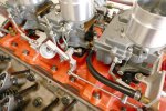
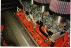
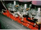
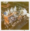
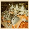
Info first: Three original Rochester 2GC [ the stamped aluminum triangular tags - center carb 7013020; rear 7013017; front 7013015 ]. I bought three rebuild kits from NAPA made by Echlin' p/n 2-5146C
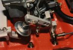
, and two p/n 2-5147 [secondary end carbs]. I verified these nos. through Echlin before I ordered from NAPA. When I originally built this engine in '95, I rebuilt the carbs then, but I believe the kits were through Big A, and don't remember who made the kits. The reason for going through them a second time was that after my run stand was completed, I ran fuel through them [4psi electric pump] and I was not getting that initial spray from the cluster ass'y. The molded rubber cups on the plunger assemblies had all shrunk and would not seal the pump wells. I installed the new kits, the primary difference being that the new pump plungers had a circular spring under the cup seal lip to put mor tension against the pump well walls. That circular spring, I believe, added too much tension, causing all three cup seals to develop a tear in the side [I lightly oiled the cup seals and pump wells first]. I called Echlin and they gave me part nos. for just the pump plunger/cup seal assembly alone [center p/n 2-4037, end carbs p/n 2-4036]. They told me that the ctr carb had a different length. I can't verify that yet, as only the ctr plunger came in, the two end plungers are coming from a different warehouse next week. The ctr plunger has no circular spring under the cup seal lip, unlike the kits I bought.
I have also checked/reset the float level, float drop, and pump rod adjustment. The main jets are #60 in ctr carb and #58 in end carbs.
I was searching some posts here and recall reading that the plunger springs were shortened. Were they the springs retained on the plunger itself, or the springs that sit in the pump well? How much were they cut and which ones?
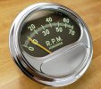
I am using a Mallory dual point distributor with no vacuum advance on it. What should the timing with this be?
The base plate for the ctr carb has a 3/8-18 NPT thread. What was this for on the original cars?
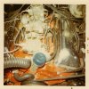
I eliminated the road draft tube and set it up for a pcv and ran it to the ctr carb base. From what I have read here, some have plugged the ctr carb base hole [which I have done]. I still have a pcv in the road draft hole in the intake manifold. Should I run it where it does not affect the fuel mixture?
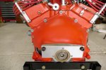
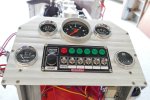
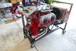
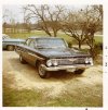
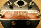
I have enclosed some pics.
Thanks,
Dick​
 

Attachments

  • P1010573.JPG
    P1010573.JPG
    84.4 KB · Views: 80
  • P1010577.JPG
    P1010577.JPG
    67.1 KB · Views: 71
  • P1010904.JPG
    P1010904.JPG
    65 KB · Views: 61
  • P1010917.JPG
    P1010917.JPG
    95.9 KB · Views: 57
  • Image (5).jpg
    Image (5).jpg
    79.9 KB · Views: 58
  • Image (4).jpg
    Image (4).jpg
    72.9 KB · Views: 65
  • Image (3).jpg
    Image (3).jpg
    102.5 KB · Views: 78

Gofish

Well Known Member
So your problem is still accelerator pump shot? If so, look in the pump well and see if there is a hole/passageway in the bottom. If so, it needs an aluminum check ball. Don’t t use a steel one - those are made for the metering jet well (under the spring secured by the ‘T’).

Let us know.

As to the PCV question, you can run the PCV hose to the large port in the rear of the base of the center carb. That’s how mine is and works fine. I put a tee there and ran the PCV out one side and the brake booster out the other.

John
 

reastman

Well Known Member
thanks, fellas.
So your problem is still accelerator pump shot? If so, look in the pump well and see if there is a hole/passageway in the bottom. If so, it needs an aluminum check ball. Don’t t use a steel one - those are made for the metering jet well (under the spring secured by the ‘T’).

Let us know.

As to the PCV question, you can run the PCV hose to the large port in the rear of the base of the center carb. That’s how mine is and works fine. I put a tee there and ran the PCV out one side and the brake booster out the other.

John
 
  • Like
Reactions: 327

reastman

Well Known Member
There is a horizontal passageway that leads to the metering jet well - has 3/16" dia steel ball in the metering jet well with a copper spring, retained by a "T". The kit diagram shows no ball in this horizontal [I should say approximate horizontal] passage. The end carbs are set up similarly, and both give a nice shot. I had a pc of .020" wire that I polished the ends and use to push into all the cluster holes, followed by a shot of Gumout. I have been looking at the pump rod adjustment carefully on the center carb, as it will squirt well with the carb top off and manually pushing the plunger into the well. The fuel level is carefully set, as well, as it appears that once the fuel level is below the edge of the well "slot", no fuel is supplied to the well. All the fuel levels were set with the electric pump and carb tops on, so I could see where fuel levels were in each bowl, before I started playing with manually inserting plunger to look at "shots" in each carb.
I haven't tried my new plunger yet. The pics of carb linkage were added to show how I set the progressive up. To determine pump rod adjustment, I made some adjustable rods first, and when adjustment done, I duplicated each rod length from single piece. The ctr carb rod is bronze-bushed, all linkage parts made from 6061 aluminum. I have a Bridgeport and lathe in my garage for my machine work - was in tool trade for 50 years.
There is no good reason why this should not work Please correct my logic if in error, as it has been a while since I worked on this engine. Perhaps some tweaking with various settings are needed.
Additionally, the center carb opens about a third of travel before secondaries are engaged. All three are full open at same time. The linkage system did present some problem-solving.
I read on this forum that some spring length was removed from plunger, the author of that statement saying the secondaries were shooting too much fuel. Any positive merits to this? Also, where should my initial timing be?
 

Don Jacks

Well Seasoned Member
Supporting Member 3
If your engine is otherwise stock[9.5-1,stock cam],use the factory settings.If you've added compression,cam,headers,set the total at 34 degrees[iron heads] by 24-2500 rpm and let the intital be what it is when the engine is returned to idle.When you have your dist.urve right,you'll usually wind up between 12-16 degrees with the vacuum advance unhooked.
 

reastman

Well Known Member
Thanks, Don
It does have 9.5 : 1, but a Crane Cams 150061 PowerMax cam. The intake valves are 5/32 larger, exh are 1/8 larger; Comp Cams1.72:1 roller tip rockers, Crane springs/pushrods, Rhoads lifters. There is no vac advance on Mallory dist.
 

reastman

Well Known Member
BTW' a few pics of the original 1961 SS. I was third owner in '68. I paid $850 with 65k on it, sold in late '69 for $675, had 90k plus miles. I still have the original tach [no sending unit - it was what failed]
 

Attachments

  • Image (14).jpg
    Image (14).jpg
    131.4 KB · Views: 46
  • Image (15).jpg
    Image (15).jpg
    136.4 KB · Views: 45
  • Image (12).jpg
    Image (12).jpg
    134.2 KB · Views: 41
  • Image (13).jpg
    Image (13).jpg
    131 KB · Views: 42
  • Image (6).jpg
    Image (6).jpg
    111.3 KB · Views: 46
  • Image (7).jpg
    Image (7).jpg
    87.7 KB · Views: 43
  • Image (8).jpg
    Image (8).jpg
    85 KB · Views: 40
  • Image (9).jpg
    Image (9).jpg
    96.6 KB · Views: 37
  • P1010581.JPG
    P1010581.JPG
    81.4 KB · Views: 36
  • P1010582.JPG
    P1010582.JPG
    66.4 KB · Views: 52

Don Jacks

Well Seasoned Member
Supporting Member 3
What are the spec's at .050 on that cam? I think that you're making a mistakeby insisting upon that non vac.advance equipped dist.Have you attempted to start it up yet? With the 9.5 piston you're limited to 220 at .050 unless you've put notches in the pistons for clearence for the valves during the cam's overlap phase.
 

reastman

Well Known Member
Duration at .050 lift: 200 intake, 210 exhaust. I checked the clearance with clay during build. I charted the offset in each piston for the wristpin [range was .060"to .0655] and took a skim cut across the 16deg gables on the piston tops in relation to the wristpin bores to make them as uniform as possible. The cam was recommended by a Chevy race engine builder. I believe the distributor was the only one Mallory had when I built the engine 27 years ago.
According to my 1961 chevy shop manual, the tappet lift on their hi-po 348 [RPO 573B] was .2319" int, and .2354 exh. At the valves w/ 1.75: 1 rocker ratio, this translates to.4058 and .412 respectively,
per manual. My Crane specs are .4668 int and .4935 exh. w/1.72: 1 ratio [1.72 :1 with the Comp Cams Magnum Roller Rocker]. This makes the Crane lobes .2714 and the exh .2869. Crane lobes .040" larger intake and .051 larger exhaust. I had Egge in California make the pistons for me and they did ask what cam I was using. There are "eyebrows" in the piston domes for valve clearance.
Yes, I have run the engine about .4 hour thus far [I have a SW hour meter wired into my run stand], and initially it started immediately after priming the oiling system and filling the carb bowls. Had the timing mechanically set at about 6 deg at the time. This is when I noticed that the ctr carb did not have a good spray but rather "dribbled" down the side of the cluster. It got a little better after the plunger cups sat in fuel for awhile, but not much. I had some minor oil and coolant leaks I repaired, and then purchased three new carb kits that had the circular springs inside the cup seal lips, which promptly tore in no time at all.
I ran it long enough to put a light on the timing [set at 8 adv and adjusted the mixture screws. I could not wrack the throttle or it would bog. I would have to get the revs up to wrack it w/o bogging.
I've never put the Mallory on a dist machine to see what kind of curve it produces. I presumed at that time that Mallory had all this worked out w/o a vac adv unit on it. I do know that at the time, Mallory was the only mfr that made a dual point dist. It was a three month wait on it because they were out of the "short shafts" used in w engines. Mallory has since sold out and you now have gotten me curious about my distributor. I'll make some inquiries tomorrow. Thanks for your knowledge, insights and interest.
Dick
 

Don Jacks

Well Seasoned Member
Supporting Member 3
I would suggest ,once you get the carbs sorted out,setting the timing at 34 degrees at 3,000rpm,then reduce the engine to idle speed and note what your initial timing is.It'll likely come in in the 12-16 range.
 

Gofish

Well Known Member
There is a horizontal passageway that leads to the metering jet well - has 3/16" dia steel ball in the metering jet well with a copper spring, retained by a "T". The kit diagram shows no ball in this horizontal [I should say approximate horizontal] passage. The end carbs are set up similarly, and both give a nice shot. I had a pc of .020" wire that I polished the ends and use to push into all the cluster holes, followed by a shot of Gumout. I have been looking at the pump rod adjustment carefully on the center carb, as it will squirt well with the carb top off and manually pushing the plunger into the well. The fuel level is carefully set, as well, as it appears that once the fuel level is below the edge of the well "slot", no fuel is supplied to the well. All the fuel levels were set with the electric pump and carb tops on, so I could see where fuel levels were in each bowl, before I started playing with manually inserting plunger to look at "shots" in each carb.
I haven't tried my new plunger yet. The pics of carb linkage were added to show how I set the progressive up. To determine pump rod adjustment, I made some adjustable rods first, and when adjustment done, I duplicated each rod length from single piece. The ctr carb rod is bronze-bushed, all linkage parts made from 6061 aluminum. I have a Bridgeport and lathe in my garage for my machine work - was in tool trade for 50 years.
There is no good reason why this should not work Please correct my logic if in error, as it has been a while since I worked on this engine. Perhaps some tweaking with various settings are needed.
Additionally, the center carb opens about a third of travel before secondaries are engaged. All three are full open at same time. The linkage system did present some problem-solving.
I read on this forum that some spring length was removed from plunger, the author of that statement saying the secondaries were shooting too much fuel. Any positive merits to this? Also, where should my initial timing be?

I may have misunderstood your initial question about the carburetor. I thought you were talking about the accelerator pump shot, but reading your first post again it seems you were asking about the main metering system. The aluminum check ball I mentioned goes in a hole at the bottom of the accelerator pump well - not all carbs had them, but if there is a hole there it needs the ball to block the fuel from returning to the pump well when the pump diaphragm pushes down the well.

John
 

reastman

Well Known Member
Looking at the PerTronix D101700 distributor. Did a lot of reading on vac adv vs non vac adv today. Tech advisor at Summit said that they have sold a great many of these and had few returns and many satisfied users. Any thoughts on this model?
 

Don Jacks

Well Seasoned Member
Supporting Member 3
Generally they are quite good,you can use stock replacement cap and rotor when a replacement part is needed.Be sure to get the recommended coil as Pertronix's electronics are rather picky about this.This unit has the Pertronix 2 system,no rev limiter.
 

reastman

Well Known Member
thanks. I currently have a Mallory coil and Mallory ballast resistor wired in. Just ordered the Pertronix. I will sell the Mallory dist. I'll have to call Pertronix about the differences between Mallory coil and theirs. I believe Pertronix has two coils for this, one is a 1.5 ohm, and other is .6 ohm.
It seems, since there will be no points, that a ballast resistor will not be necessary. Is this correct? Also, best place to supply vacuum to dist? Chevy shop manual calls for hollow stud securing base of rear carb as supply. If I do this, I presume the hole diameter should be same as nipple on vac adv.
Dick
 

Don Jacks

Well Seasoned Member
Supporting Member 3
Yes,a ballast resister is not required.The hollow stud is what the factory used and has adquate area for the vac..advance.I believe,according to their website, that the .6 ohm is what is wanted for the Pertronix 2 module.
 

reastman

Well Known Member
I talked to Chris @ Pertronix yesterday. He said that model D101700 requires PORTED vacuum, and if I used manifold vacuum, their dist would pull open 40deg of advance as soon as engine is started. He said that the vacuum fitting at center carb base is manifold vac. My center carb is GM # 7013020, the correct factory carb. I cannot find anything about ported vacuum on this model [ see pg 7-21 of 1961 factory shop manual, using hollow stud, which is manifold]. It seems to me that the vacuum cannisters all pull open [GM or otherwise] when vacuum is applied. If I understand all this correctly, ported vacuum increases with higher throttle, whereby manifold vacuum decreases with more throttle. I believe he also said that ported vacuum must originate above throttle plate. Looking at the bottom of the ctr carb base, I see that the 3/8-18 npt fitting goes into a small cavity that has small channels that go to the venturi wall. It would seem that this is ported, however it is below throttle plate. I also read somewhere that this also leads down to manifold into plenum, thus making it manifold vacuum. The Pertronix is made for the 348/409, and requires ported vacuum. My carb no. is correct for '58 - '61 3x2 set up. So where is the ported vacuum? The only thing I can deduce is that the GM dist is internally linked to work opposite the Pertronix.
I cancelled my Summit order for the Pertronix until I get this sorted out.
One other Q: Who on this forum is running an aftermarket vac adv dist , what brand and model, how is the vac supplied?
Thanks,
Dick
 
Top