Oil Temp

reastman

Well Known Member
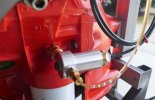
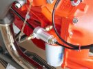
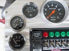
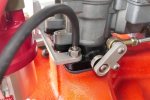
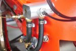
Open to suggestions for mounting an oil temp sending unit, a mechanical style. Stewart warner instructions vague, other than being in oil flow. I've heard of oil filter base adapters and drain plug adapters. I don't know if there is enough flow behind the block-off plate for mechanical fuel pump [presently using an electric pump], but I made an aluminum plate that would be easy to tap [unit has a 1/2-14NPT fitting]. My oil pressure is pulled from the 1/4-18NPT hole above the oil filter.

Dick
 
  • Like
Reactions: 327

reastman

Well Known Member
Been awhile since I had that plate off - "splash" lubrication on pump arm, I believe
You will be measuring the air temp more than the oil at the block off plate. Oil pan is the best.
Drain plug hole, or bulkhead-type fitting in the side of pan?
 
  • Like
Reactions: 327

blkblk63ss

Well Seasoned Member
Supporting Member 5
Just for ease of installation and a good flow of oil why not tee in oil pressure sender fitting.would require another fitting adaptor of course.
 
Last edited:

reastman

Well Known Member
Without draining the oil right now to measure, what is the thread size for the drain plug?
In my 34 coupe i welded a fitting in the lower side of the oil pan and back in the dirt track days i did the same thing its surprising how long it takes the oil temp to come up
The oil did get to 145, but took a while to get there, maybe 20 mins.
Just for ease of installation and a good flow of oil why not tee in oil pressure sender fitting.would require another fitting adaptor of course.
I'll post a pic of the "T" I made. I just don't know how much flow is present.
 

reastman

Well Known Member
Just took these. The "T" that I made has 1/4 NPT on end and two sides. The 1/2 NPT has the oil temp sender in it. The sender "bulb" is about 3/8" diameter and goes through the 1/2NPT fitting. The tap drill size for 1/2NPT is .718", and reaches to the 1/4NPT fittings, one of which goes to block and the other to oil pressure. I don't know if there's any circulation there. I tend to think once the bulb cavity fills, there is only pressure. On the other hand, as the oil warms up, it all warms up. The coolant in the block is not far from all this.

The other pics are two hollow studs in front and rear throttle plate bases, and both have same vacuum, unlike center base which has the PVC attached. The rear hollow stud goes to gauge and the front is reserved for a vac advance distributor.
 

Attachments

  • P1020007.JPG
    P1020007.JPG
    55.2 KB · Views: 30
  • P1020006.JPG
    P1020006.JPG
    74.1 KB · Views: 31
  • P1020008.JPG
    P1020008.JPG
    79.4 KB · Views: 27
  • P1020009.JPG
    P1020009.JPG
    61.2 KB · Views: 25
  • P1020010.JPG
    P1020010.JPG
    65.7 KB · Views: 24
  • P1020011.JPG
    P1020011.JPG
    61.2 KB · Views: 24
  • P1020012.JPG
    P1020012.JPG
    59.4 KB · Views: 29

blkblk63ss

Well Seasoned Member
Supporting Member 5
Seeing the adaptor or tee i sugested it looks like it would take some time to show correct oil temp being not much flow. I see your oil filter direct to block. I thought going from cannister oil filter required a adaptor to spin on filter. Could you possibly make a block spacer with tapped holes between block and filter for temp sender connection.There the flow would be greater. Just wondering if that was possible since you seem to be able to make your own parts. Very nice craftsmanship .
 
Last edited:

reastman

Well Known Member
Seeing the adaptor or tee i sugested it looks like it would take some time to show correct oil temp being not much flow. I see your oil filter direct to block. I thought going from cannister oil filter required a adaptor to spin on filter. Could you possibly make a block spacer with tapped holes between block and filter for temp sender connection.There the flow would be greater. Just wondering if that was possible since you seem to be able to make your own parts. Very nice craftsmanship .
I did put on a spin-on adapter - just doesn't show in the pic. I may have to make as you suggest - it would look factory.
Not the most accurate method but better than nothing.
I agree. That's why I'm considering better alternatives - and why I value the collective expertise here on this forum. As they say, "back to the drawing board".
 

reastman

Well Known Member
I bought a Perma-Cool "sandwich oil adapter" that is used with their oil coolers. It is mounted between the spin-on adapter and the filter and has two 3/8 NPT holes to install a hose barb oil line hose. I ran the two lines into a manifold I made so that the oil temp sending unit is now in the oil flow. I mounted the unit to a bell housing hole.
I also got my distributor [OEM 409] set up with a Pertronics Ignitor and a 40K volt coil with 1.5 Ohms resistance, as per factory recommended. Increased plug gap to .040". The Ignitor requires certain clearances between the module and magnets, so I ended up making a shim from some aircraft valve guide bronze I had on hand, I can't remember the bronze designation, but had bought it when I made new guides for my '66 Honda 305 SuperHawk. This stuff is very wear-resistant and work-hardens in service. The distributor itself is in excellent condition, with no measurable wear anywhere. I did put a new vac can on it, however. It mounted on the manifold with cylinders one and two indexed to the dist position as shown in the oem shop manual.
The vacuum is supplied by a hollow stud I made for rear carb and the gauge supplied by a hollow stud in front carb.

On another note, I saw several sending units at a car show/swap meet this weekend. The tach head shown is the factory original from my '61 S/S. What is the correct sending unit model and what should I expect to pay?

My other question is what are the casting numbers for the correct exhaust manifolds for the 335 hp 348 I had in my '61?
 

Attachments

  • P1020013.JPG
    P1020013.JPG
    62.4 KB · Views: 31
  • P1020014.JPG
    P1020014.JPG
    56.7 KB · Views: 27
  • P1020016.JPG
    P1020016.JPG
    70.9 KB · Views: 23
  • P1020015.JPG
    P1020015.JPG
    80.1 KB · Views: 19
  • P1010581.JPG
    P1010581.JPG
    81.4 KB · Views: 20
  • P1010582.JPG
    P1010582.JPG
    66.4 KB · Views: 29

blkblk63ss

Well Seasoned Member
Supporting Member 5
I bought a Perma-Cool "sandwich oil adapter" that is used with their oil coolers. It is mounted between the spin-on adapter and the filter and has two 3/8 NPT holes to install a hose barb oil line hose. I ran the two lines into a manifold I made so that the oil temp sending unit is now in the oil flow. I mounted the unit to a bell housing hole.
I also got my distributor [OEM 409] set up with a Pertronics Ignitor and a 40K volt coil with 1.5 Ohms resistance, as per factory recommended. Increased plug gap to .040". The Ignitor requires certain clearances between the module and magnets, so I ended up making a shim from some aircraft valve guide bronze I had on hand, I can't remember the bronze designation, but had bought it when I made new guides for my '66 Honda 305 SuperHawk. This stuff is very wear-resistant and work-hardens in service. The distributor itself is in excellent condition, with no measurable wear anywhere. I did put a new vac can on it, however. It mounted on the manifold with cylinders one and two indexed to the dist position as shown in the oem shop manual.
The vacuum is supplied by a hollow stud I made for rear carb and the gauge supplied by a hollow stud in front carb.

On another note, I saw several sending units at a car show/swap meet this weekend. The tach head shown is the factory original from my '61 S/S. What is the correct sending unit model and what should I expect to pay?

My other question is what are the casting numbers for the correct exhaust manifolds for the 335 hp 348 I had in my '61?
Very nice. Only I would have opted for steel lines instead of rubber hose's.Also, you might have to tuck those lines in for clutch linkage maybe????
 
Last edited:

55Brodie

Well Known Member
I bought a Perma-Cool "sandwich oil adapter" that is used with their oil coolers. It is mounted between the spin-on adapter and the filter and has two 3/8 NPT holes to install a hose barb oil line hose. I ran the two lines into a manifold I made so that the oil temp sending unit is now in the oil flow. I mounted the unit to a bell housing hole.
I also got my distributor [OEM 409] set up with a Pertronics Ignitor and a 40K volt coil with 1.5 Ohms resistance, as per factory recommended. Increased plug gap to .040". The Ignitor requires certain clearances between the module and magnets, so I ended up making a shim from some aircraft valve guide bronze I had on hand, I can't remember the bronze designation, but had bought it when I made new guides for my '66 Honda 305 SuperHawk. This stuff is very wear-resistant and work-hardens in service. The distributor itself is in excellent condition, with no measurable wear anywhere. I did put a new vac can on it, however. It mounted on the manifold with cylinders one and two indexed to the dist position as shown in the oem shop manual.
The vacuum is supplied by a hollow stud I made for rear carb and the gauge supplied by a hollow stud in front carb.

On another note, I saw several sending units at a car show/swap meet this weekend. The tach head shown is the factory original from my '61 S/S. What is the correct sending unit model and what should I expect to pay?

My other question is what are the casting numbers for the correct exhaust manifolds for the 335 hp 348 I had in my '61?
Very nice work. A couple of comments....you may want to reverse the one hose clamp with the screw head pointed inboard for future serviceability. Also, I would use teflon pipe sealant rather than what I think is tape that I'm seeing.
The correct tach sender is EB9A. You can no longer get the correct batteries for them, however.
Here is a simple, inexpensive solution.
 

reastman

Well Known Member
Very nice work. A couple of comments....you may want to reverse the one hose clamp with the screw head pointed inboard for future serviceability. Also, I would use teflon pipe sealant rather than what I think is tape that I'm seeing.
The correct tach sender is EB9A. You can no longer get the correct batteries for them, however.
Here is a simple, inexpensive solution.

Very nice. Only I would have opted for steel lines instead of rubber hose's.Also, you might have to tuck those lines in for clutch linkage maybe????
Thanks for the input. When it actually goes into a car, changes will be made then.
 

pvs409

Well Known Member
Supporting Member 11
The best way to convert your 61, 62 factory tach and sender ( use any good sender box that looks like a EB-9A) and send the tach and sending unit to Williamsons instruments in Arkansas and they will convert the tach to electronic so the factory set works as they should. The work on the tach & sender is warranted for as long as you own the tach.

I have converted all my factory tachs to electronic much better than some add on convertor.
the correct 1961 high horsepower 348 manifolds are
3767583
3767584

these numbers are listed in the home section of this forum
Paul
 

63 dream'n

Well Seasoned Member
Supporting Member 4
Wouldn’t the steel lines wick off more heat……. I would think the rubber hose would isolate or insulate, and give a better true reading…..???
Beautiful work by the way……!!!!
 

blkblk63ss

Well Seasoned Member
Supporting Member 5
Wouldn’t the steel lines wick off more heat……. I would think the rubber hose would isolate or insulate, and give a better true reading…..???
Beautiful work by the way……!!!!
Well if that's the case ,then that wouldn't be a bad thing since the concern is keeping an eye on oil temp in the first place going to high. Any way there is enough circulation I don't think it make's any difference to speak of.
 
Top