409 in a 1935 chevy

jwhotrod

 
Supporting Member 1
right now we have the heads off, the original thinking as misguided as it was, that we had a blockage between the head and the block. I did have it running enough on Friday before the tear down to make sure it was building pressure and didn't have any nasty noises in it. I don't think I hurt it Thursday. Models that is a good idea when we get the heads back on, I will prime it to see. I'm kinda stuck with an adapter sleeve of some kind due to the accel dual phase distributor that runs the EFI does not come in 409 version. As I said above, we are modifying the oil return holes in the heads as a "doesn't hurt anything and why not as long as its apart." It is crazy I know, but one way or the other this will get resolved. It would be a monumental task at this point to change engines as all the primary systems have been built specifically to support this engine. Steering, exhaust, cooling, AC/heat all are effected, so it is not as easy as just going to get a LS takeout, or E-Rod package nothing just bolts in.
Thanks
Big Jim
 

Ronnie Russell

Well Known Member
Supporting Member 2
Jim, It seems that Rob Walden would be able to offer a suggestion about the problem. They do offer EFI units , so , maybe he has information that might help. :dunno
 

jwhotrod

 
Supporting Member 1
Thanks Ronnie, we were talking at breakfast this morning, and the thought arose that it could be as simple as venting the valve covers to relieve a potential vacuum conditions similar to a gas can? It cant hurt like everything else, we shall see.

Big Jim
 

jim_ss409

Well Known Member
Supporting Member 5
Thanks Ronnie, we were talking at breakfast this morning, and the thought arose that it could be as simple as venting the valve covers to relieve a potential vacuum conditions similar to a gas can? It cant hurt like everything else, we shall see.

Big Jim

It's hard to say if venting the valve covers would help. I certainly get the idea that they should drain better with a vent, like venting a gas can as you said. But you also have to consider the crankcase pressure. If there is any pressure in the crankcase it will push it's way up into the area beneath the valve covers and out the vents. The only way it can get there is through either the pushrod holes or the oil return holes. :scratch The incoming air might stop or slow the progress of the outgoing oil.
I'm not sure about that, after all a lot of guys have vented valve covers and have no problems.
I think modifying the oil return hole as you described is a good idea. It might also be good to grind a radius on the top of the hole to help the oil funnel down into the hole easier. It would be nice if you could just drill the hole a size or two bigger but it's pretty close to the head bolt so that could be a problem.
I notice that external oil drain lines are quite common on race engines and I know part of the reason is to prevent excess oil from draining into the valley and down onto the spinning crank, but I'm sure part of the reason is to just be sure the oil gets back down to the pan as quickly as possible.
I remember Curt Harvey saying that oil return could be a problem with a high volume oil pump. I always thought that even if the drains didn't keep up, the oil would just run down the pushrod holes before the pan ran dry, but when I look at the pushrod holes, they're fairly high up so there would be quite a bit of oil in the heads by the time it reached the holes. Also, the pushrod holes are not all that big so they might not let the oil out quickly enough either. :dunno
 

Ronnie Russell

Well Known Member
Supporting Member 2
We must ask ourselves, why is this the only 409 engine with a stock pan that can check zero on a correct dipstick after engine is turned off. The oil pump used is not a high volume. There is no reason I can think of why 7 qts of oil would be in the top end. The valve cover breathers will help by allowing a viewing access to the area under the valve covers. That's the only benefit they will provide. Without a vacuum pump, there is positive crankcase pressure trying to push out. No way is there vacuum under the valve covers. The stock oil drain back holes in the heads work for everyone else, why is this one different? I can't see cleaning the heads up and relieving the oil drain backs will allow 7 qts of oil to get back to the pan much quicker. It shouldn't be there to begin with. Still, a mystery.
 

boxerdog

Well Known Member
Supporting Member 5
I always thought external lines from the rear of the heads directly to the pan would be a good idea, but I haven't tried it yet. Like Ronnie said, most of the engines drain OK, why is this one different?? After messing with primers at one point, I am a little suspicious of the sleeve, I have seen cases where the valley got more oil than the top end...but even then it should drain back quickly if it isn't trapped in the head???? I hope the answer turns up and no real damage has been done.
 

jwhotrod

 
Supporting Member 1
I don't know for sure my self, it remains a mystery. The only thought here is as I said if you turn a gas can upside down without opening a vent on top gas just gurgles out, open the vent and it is almost instantly empty. So we thought maybe the PCV/vent setup in this manifold is not doing a good enough job of venting the valve covers. This is a custom built sheet metal manifold and the breather is placed in the front of the valley pan about where the oil fill tube would be in a stock manifold. It is a K&N breather filter. The PCV valve is mounted in the same valley pan about 7" behind the breather. and vacuum fitting in the plenum below the throttle bodies. So maybe it is doing ok at balancing crankcase pressure but not putting enough draw in the engine to vent the solid valve covers?? Stranger things have happened. Now I am not saying that the oil will whoosh out after doing this, but something has disrupted the balance in the oil system and this sounded like a logical path to take. So I ordered 2 right angle breathers from Moon today and we are going to try it. Again no harm and it just may help. attached is a photo of the modification is.modhole.jpg
 

oldskydog

Well Known Member
Supporting Member 10
Jim,
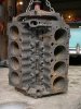
I believe you said your engine was a 64, that would make it a 422 casting. There was a change in the block for 64. Does your block have this hole?
Do you have a vented oil filler cap or sealed?


This is the main change to the block design and adds a big vent to equalize the pressure between the crankcase and the lifter valley. I believe this change occured with the beginning of 64 production.
The draft tube was replaced with a positive vent system that reversed the flow and now took fresh air for the crankcase from the air cleaner into the back of the block where the road draft tube was. The oil fill breather cap was replaced with a sealed cap and PCV valve attached to the oil fill tube and hose to a manifold vacuum source at the base of the carb. The big hole in the front china wall should eliminate most of the drainback problems caused by the drain slots trying to serve simultaneously as both oil drains in one direction and vents in the other direction.

Prior to this change, the oil filler tube cap served as the intake breather directly to the crankcase on the front side of the china wall behind the timing gear and then the air would have to work it's way up through the cam area drain slots in the lifter valley floor against the drainback flow of oil. The lifter valley was then vented through the oil splash shield on the bottom of the intake and then out the road draft tube. The road draft tube had an angle cut on the bottom to use the outside air while in motion to help scavenge the air/vapors from the engine. The problem with this is that if the crankcase is over pressurized or insufficiently vented, that pressure coming up around the cam, through the lifter valley drain slots over the cam hinders the oil in the valley from draining back into the pan and the pressure can build up in the valley preventing the oil on top of the heads from draining into the valley.

I see the problem, or at least part of the problem likely to be in your venting system as Jim_SS409, Ronnie and you have already mentioned.
The original oil pump moved 4.3 gals per minute @ 2000 rpm...doesn't take long to empty a pan a that rate.

JMHO
 

jwhotrod

 
Supporting Member 1
Yes, that big hole is in the china wall as you describe, so I think we are going in the right direction, at least I hope so. Logic would say that placement of these things shouldn't have that much effect, but you and I both know sometimes logic has little to do with the outcome. Thanks for your attention and research, it is a great help. The ultimate power of this forum is the collective brain power and wisdom that we all have access to.

Thanks again
Big Jim
 

DonSSDD

Well Known Member
Supporting Member 2
Do you have an old valve cover that you can cut a slot out of so you can see what is going on when you start it the next time? Like is used for hot setting the valves?

Don
 

jwhotrod

 
Supporting Member 1
I do not, however we got the heads back on yesterday and ran a small block primer tool in the adapter sleeve and block before we reinstalled the intake manifold. We had modified the oil return holes in the heads to be .450' dia all the way thru. The original cast hole from the spring side tapered with the casting draft down to almost 3/8" and made sure the hole from both sides fully intersected also cut back the casting below the drain holes in the cam valley side of the heads to the edge of the block to shorten the oils path as much as we could. When we primed the engine, we saw that the adapter sleeve was doing its job, venting oil into the cam galley thru the various holes in the block casting and pushing oil up into the cam galleys and push rods. As soon as oil began to pool in the bottom of the "w"s the oil began to run out of the drain holes and into the cam galleys so we feel we made that much of the concern much better. I received breathers from Mooneyes yesterday and installed same on valve covers, I need to diddle with the timing somewhat this morning tried to start it last night and it wants to run but ran out of time because of outside commitments. I will post pictures later, but I think we have a handle on the situation. If this is successful, I am sure the cause was something I did in setting up this custom manifold, so it would be in great part a unique set of conditions that caused this. If you think of what Cecil said about the pump generating 4.3 gpm that means the oil in the motor turns over almost 3 times a minute, so it would not take a lot to disrupt the balance in the system. I placed both the vent (breather) and PCV valve in the valley pan of the manifold with the breather in front about where the oil fill tube would be, half the length of the engine back I placed the PVC valve also in the valley pan. So entire ventilation system was concentrated in the cam valley, so if air and liquids take path of least resistance what would encourage the valve covers to vent? If they don't vent then it could cause all of this rushing oil to build up in the valve covers and not drain "gas can effect". So like I said later today I should have an answer as to whether or not we are successful. Logic would say so, but as I said sometimes logic has nothing to do with it.
Big Jim Pictures to follow later today.
 

oldskydog

Well Known Member
Supporting Member 10
Jim, you made mention several times that you had a 7 quart pan. Is it a custom pan or a stock truck pan?
Truck pans were 6 quarts and one in the filter unless you have the optional 2 qt filter.
7 qts in a 6 qt pan would likely foam the oil, I would think.:scratch
 

models916

Well Known Member
Supporting Member 7
Road draft tube vents the lifter galley, the big hole in the top is to vent the bottom end thru the timing chain passage. If you didn't drill the hole, you have to make sure your breather allows the timing cover area to vent out without much crossover into the valley.
 

Attachments

  • oil vent.jpg
    oil vent.jpg
    76.5 KB · Views: 3

jwhotrod

 
Supporting Member 1
It is a stock 6 quart car pan I think, I am not sure how to tell other than with a "stock" dipstick it says its full with 6 quarts in it and the motors manual says it is a 6/7quart system. I did start out with 6 quarts in the pan and 1 quart in the filter. But seeing that it was emptying the pan, I added another quart to the pan in an attempt to overcome the deficiency and I believe there is room enough under the windage trays to add another quart without getting into the crank. As to the road tube, I don't have one, this is a custom built sheet metal manifold and did not have ventilation or water provisions built into it. That is what I said way back in the beginning, just because someone does custom work like that and says they are done, does not mean it is finished or complete. That said, I had added a vent and a PCV valve to the manifold, but obviously I was less than successful in my placement. So onward and upward, I am not sure what hole you are asking me if I drilled or not, but the breathers seem to have done the job along with the modifications we did to the drain holes in the heads.
 

62impala409

 
Supporting Member 1
Jim, see the photo in Cecil's post #148 that shows the big hole above the camshaft in the China wall that allows the pan to vent through the timing chain area to the lifter valley and out the road draft tube. Leo
 

oldskydog

Well Known Member
Supporting Member 10
Jim, see the photo in Cecil's post #148 that shows the big hole above the camshaft in the China wall that allows the pan to vent through the timing chain area to the lifter valley and out the road draft tube. Leo
Actually, that hole was part of the change in the venting system which had previously been from front to rear . The change reversed the flow to rear to front, so no road draft tube. The fresh air entered the engine from the base of the air cleaner, through the old draft tube hole in the back and exited through the oil filler tube, PCV valve and into the induction system at the base of the carb.

I wouldn't be surprised if your little breather was clogged with oil on the bottom.
 

62impala409

 
Supporting Member 1
Cecil has it correct. I should have quit typing before I got to the road draft tube part. They were last used on the '62 motors. Leo
 

oldskydog

Well Known Member
Supporting Member 10
Cecil has it correct. I should have quit typing before I got to the road draft tube part. They were last used on the '62 motors. Leo
Wasn't trying to step on you, Leo. I just wanted to be sure everybody understands the history of the crankcase vent system.
Eveytime somebody presents a problem like this, I have to search for something I remember reading about before and it forces me to analyze and better understand the "why" behind these things and how they work. Even then, I still get it wrong sometimes.
 

models916

Well Known Member
Supporting Member 7
Passenger pan the drain plug faces forward and the truck pan plug faces down. The added quart on the truck is for the super big filter on the trucks. Both pans are 5 quarts. 348 passenger is 4 quarts. Truck pans on both 348 and 409 were 5 quart.
 

tripower

Well Known Member
Supporting Member 2
Passenger pan the drain plug faces forward and the truck pan plug faces down. The added quart on the truck is for the super big filter on the trucks. Both pans are 5 quarts. 348 passenger is 4 quarts. Truck pans on both 348 and 409 were 5 quart.

Mike, Are you saying then the 409 passenger and all 348-409 truck pans are 5-quarts plus 1-quart for the filter for a total of 6 and, the 348 passenger pan is 4-quarts plus 1-quart for the filter for a total of 5?
 
Top