I've seen valve cover rails machined pretty crappily. I'd think the prefered method would be to measure at the pan rail, but that may be difficult. 


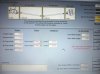
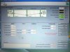
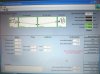
 But there could still be a problem because I left the phase angles at 0 degrees. I can't remember for sure but I think the driveshafts on these cars might be phased at 90 degrees. For that matter I might be confused about what 90 degree phasing looks like. I'll check it out a little later and report back on that.
I've seen valve cover rails machined pretty crappily. I'd think the prefered method would be to measure at the pan rail, but that may be difficult.

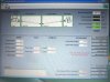
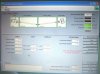
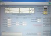
Here's the last three...
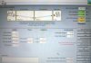
Can I get you to run another set of numbers?
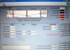
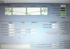
Engine 2.9 down in rear
First shaft .9 down in rear
2nd shaft 1.0 UP in rear
Pinion 1.0 down
.82 fifth gear
28" shafts
Thanks, Kevin.
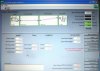
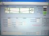
Shouldn't both my phase angles be ZERO on my Inland Empire shaft? Can you run both at zero phase and check again? Thanks, Kevin.
 The program defaults to 90deg. I forgot to change it. By the way, I double checked in the descriptions section and we're right about what a 90 or 0 degree driveshaft looks like.